The 4-20 mA analogue output signal dominates the process control industry. With this blog post, you will learn about its principles of operation as well as its advantages and disadvantages so that you can make informed decisions about process control.
In the modern world, which would not exist in its current form without process control, there are countless different types of process inputs. One type is analogue signals found, for example, in thermocouples and resistance temperature sensors. Another is digital signals, through which process variable can be accurately controlled and data displayed.
However, it is analogue signals, particularly 4-20mA, that are currently the dominant input type and standard for signal transmission in industries requiring process control. They are often used in the transmission of values such as temperature, pressure, humidity or flow.
There are two types of sensors by signal:
digital – a discontinuous, discrete voltage signal. They send information in the form of bits.
analogue – continuous signal. They convert non-electrical environmental parameters into an electrical signal.
The 4-20 mA loop current is a simple analogue method of transmitting information from sensors.
sensor – the circuit that converts the measured physical value into an electrical value.
current loop converter/transmitter – converts the sensor output signal into a current signal compatible with the 4-20 mA current loop standard.
DC voltage source – usually 24 V.
current loop consisting of connection wires. These have their own wire resistance, which must be factored into the current loop budget. This is particularly important for long cables.
receiver – the device that receives and reads the measurement results.
current loop budget – for a current loop to function properly, it needs a positive energy budget. To calculate it, you need to know the maximum dc power supply voltage in the loop and the level of minimum supply voltage or resistance of all components.
The loop consists of four elements: a graphic recorder, a receiver, a transmitter and wires.
Knowing the resistance of the recorder and the receiver, it is possible, using Ohm's law, to calculate the voltage drop across these elements.
standard in many industries – ease of connection
greater immunity to background electrical noise and interference – electromagnetic interference is transferred to the signal line as voltage signals, thus causing negligible changes in current and input resistance of the receiver
easiest option to connect and configure
less wiring, what means less setup costs
best choice for long distances transmission – current in a 4-20 mA loop does not degrade as much as voltage in long connections
simple fault detection (e.g. whether the sensor cable is damaged) due to the 4 mA current being equal to 0% of the output power
high current consumption compared with a sensor that has a voltage signal
requires an excitation voltage of at least 10 VDC, which limits the possibilities of battery supply
4-20 mA current loops can only transmit one specific sensor or process signal per loop.
For applications where there are multiple sensors or process outputs that need to be transmitted, multiple loops are required
a large amount of field wiring is required, which can lead to serious ground loop problems if the independent current loops are not properly isolated from each other
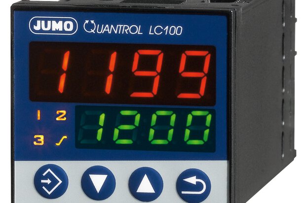
Most JUMO compact controllers have universal analogue inputs to which components such as a sensor are connected for recording the actual value. In measurement and control technology, the transmission of the measured value is carried out using standard signals. A current signal of 4 to 20 mA is mainly used for this purpose, but 0 to 20 mA, 2 to 10 V and 0 to 10 V signals are also available. The graphic shows the transmission of information about the measured pressure value using a 4 to 20 mA signal:
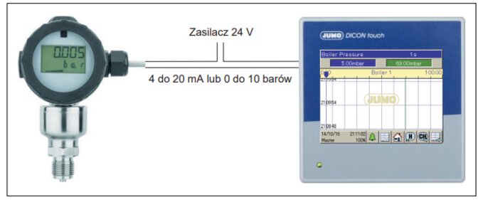
4..20 mA transmitter – connection and analogue measurements
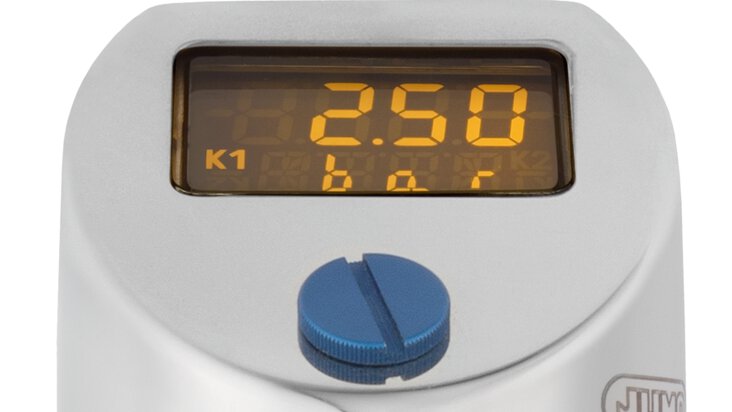
The JUMO dTRANS p20 pressure transmitter shown measures the relative pressure from 0 to 10 bar and transmits this information to the JUMO DICON touch process and software controller via a 4 to 20 mA analogue signal. The universal controller input is set to 4 to 20 mA and scaled to 0 to 10 bar. The measured pressure value is available in the controller and all settings refer to the scaled unit (bar). The power supply provides the voltage supply to the pressure transmitter.
JUMO has a wide range of sensors with analogue 4 20 mA output, e.g. the pt100 temperature sensor with integrated 4 20ma current loop transmitter JUMO E temp B.