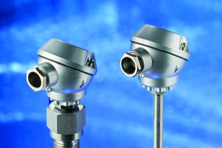

Thermocouple compensating cable – tolerance classes, colors, using
Thermocouple compensating cables are used to connect thermocouple sensors to remote connection points such as control cabinets, gauges, regulators, etc., making it possible to transmit the sensor signal over long distances without signal loss and connect to processing units. From our article you will learn, among other things, how to read the markings of the mentioned wires, their colors and tolerance classes. Read on!
How does a thermocouple work?
Thermocouples are temperature measuring devices with a thermocouple – a combination of two wires made of different materials – as the measuring sensor. In addition to the aforementioned thermocouple, they consist of a wire that connects the measuring junction to a reference point, or terminals.
One end of the thermocouple is connected in what is known as the measuring junction, while the free ends on the other side are terminals, where the voltage created by the thermoelectric effect is measured.
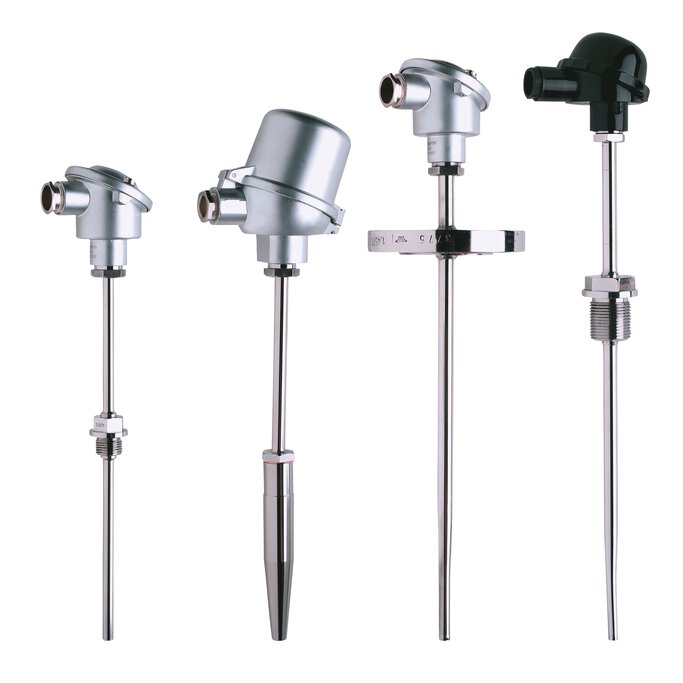
Screw-in thermocouples
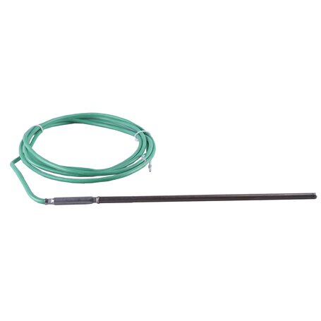
Thermocouple with cable
Thermocouple – connection
In most cases, a thermocouple is connected to another measuring device by means of connecting wires. Among them we distinguish extension and compensation wires.
Compensation cable – what is it?
Compensation wires are designed to connect thermocouples to measuring devices. They are made of a material that has the same electrical characteristics as the thermocouple in the temperature range allowed by DIN EN 60 584, so as not to falsify the measurement results. For example, for a type K thermocouple, the compensating conductors are made of the following types of conductors: Fe/Cu-Ni, Ni/Cr-Ni or Pt-Rh/Pt.
The compensation wire consists of "+" and "-" conductors, which produce the same thermoelectric voltage as the thermocouple at connection point temperatures up to 200°C.

Thermocouple connection – diagram
Compensating cables – designations
Compensation cables are available in various insulations, protective sheaths and with multiple conductors. They are marked with a color code and a letter distinction with the following meaning:
-
1. letter: letter distinction of the type of thermocouple according to the standard
-
2. letter: X - same material as thermocouple; C - special material
-
3. letter: in the case of more types of equalizing conductors, the third letter is used
Example:
KX: compensation wire for NiCr-Ni thermocouple type "K", made of the same material as the thermocouple
RCA: compensation wire for PtRh-Pt thermocouple type "R", made of special material type A
Tolerance class of compensation wires for temperature measurements
Two tolerance classes have been defined for compensation wires: 1 and 2. Class 1 ma is achievable only for thermocouple wires made of the same material as the thermocouple (type X). Class 2 compensation wires are supplied as standard.
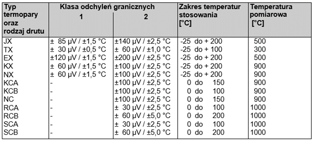
The application temperature range means the temperature to which the entire cable, including the terminals connecting it to the thermocouple, can be exposed, "so that the tolerances given in the table are not exceeded. Due to the nonlinearity of thermocouple voltages, the specified limit deviations in µV or °C refer to the measurement temperature, given in the right-hand column.
Specifically, this means, for example:
A thermocouple of type J is connected to a compensation wire of type JX, class 2. If the measuring temperature is fixed at 500 °C and the temperature at the terminals and/or the temperature of the compensation wires varies between -25 °C and 200 °C, the indicated temperature varies by ±2.5 °C at most.

The tolerance of the temperature indication with a type "J" thermocouple connected via a class 2 "JX" compensation cable is 2.5°C
What is the difference between a compensating cables and an extension cables?
Compensation and extension (thermoelectric) cables are components of a measurement system that connect a thermoelectric sensor to a measuring device, such as a controller, temperature recorder or indicator.
The main difference is that compensation cables are made of substitute materials with the same thermoelectric properties as the thermocouple, and extension wires consist of the same materials as the thermocouple.
Compensation cables - the purpose of application
The voltage developed at the ends of the thermocouple is proportional to the difference in temperature of the measuring junction and the reference temperature. The characteristics of thermocouples in the standards are given for a reference temperature of 0˚C. Only at this value it is possible to use the arrays without making corrections to the measured values.
However, while in laboratory conditions it is possible to achieve a reference temperature of 0˚C by placing the reference point in ice water, this is not possible for industrial measurements - in such conditions the temperature near the sensor installation fluctuates.
This problem is solved by compensation cables - they move the reference junction away from the location where ambient temperature fluctuations are relatively small.
Compensation wires - colors
For thermocouples according to DIN EN 60 584, the following rule has been established: the positive arm (plus) has the same color as the sheath, and the negative arm (minus) is white. However, for the "old" type "U" and "L" thermocouples according to DIN 43 713, other markings have been adopted:
The only exception to this is the intrinsically safe circuit wires in equipment suitable for use in hazardous areas. Insofar as they are colored, the sheath of all compensation wires is light blue, while the color of the conductors is in accordance with the color codes specified (Blue color of Cu-CuNi thermocouple according to DIN 43 713 is dark blue).
Note that the color coding may vary depending on the standard!
JUMO thermocouple markings - example
Example of marking with green color of thermocouple type K:
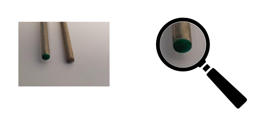
Example of JUMO's K-type thermocouple marked in green
Compensation cables for thermocouples
Compensation cable for K thermocouple
The screw-in type K thermocouple with compensation cable from JUMO is available in various versions and has a compensation cable k in silicone or with metal braid. Depending on the version, the compensation cables are suitable for use in dry and humid areas in the temperature range from -20 to +350°C.
Type J compensation cable
JUMO sheathed thermocouple with compensation cable has a type J, K or L measuring insert available. Depending on its design, the cable can be used in both dry and wet process environments. The operating temperature of this thermocouple ranges from -200 to 600°C.
- ${title}${badge}
